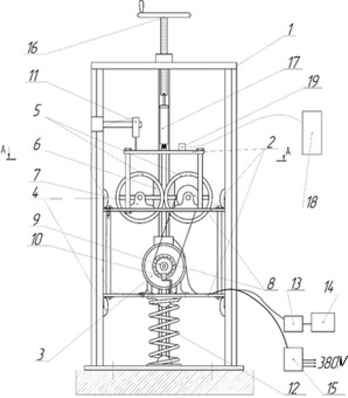
Fig. 2.
Download original image
General diagram of vibration stand for test: 1-base, 2lower, middle and upper platforms, 3-electric motor, 4-support rollers, 5-drums, 6-load, 7-bearing units, 8-master and driven sprockets, 9-driving disk, 10-optical slot sensor, 11-linear displacement sensor, 12-spring, 13-analog-to-digital converter, 14-computer, 15-three-phase frequency converter, 16-screw type base, 17-test device, 18-noise meter-vibrometer, 19accelerometer.
Current usage metrics show cumulative count of Article Views (full-text article views including HTML views, PDF and ePub downloads, according to the available data) and Abstracts Views on Vision4Press platform.
Data correspond to usage on the plateform after 2015. The current usage metrics is available 48-96 hours after online publication and is updated daily on week days.
Initial download of the metrics may take a while.