| Issue |
BIO Web Conf.
Volume 27, 2020
International Scientific-Practical Conference “Agriculture and Food Security: Technology, Innovation, Markets, Human Resources” (FIES 2020)
|
|
|---|---|---|
| Article Number | 00056 | |
| Number of page(s) | 6 | |
| DOI | https://doi.org/10.1051/bioconf/20202700056 | |
| Published online | 25 November 2020 | |
Hydraulic system for agricultural tractors adapted to alternative fluids
Samara State Agrarian University, Samara, 446442, Russia
* Corresponding author: This email address is being protected from spambots. You need JavaScript enabled to view it.
Abstract
The article analyses the main factors affecting the performance of tractor hydraulically mounted systems. Adaptation of hydronic system for using a vegetable-mineral lubricating composition as a working fluid is considered. A scheme of a modernized hydraulic system, supplemented by a centrifugal cleaning unit as well as means for targeted alloying of the working fluid with additives is proposed. The results of a centrifuge study with specified parameters (rotor height H=137 mm, rotor diameter d=148 mm, rotor speed 5000 ± 50 min–1) showed its effectiveness for cleaning the working fluid from the most dangerous abrasive particles. The results of operational tests showed a decrease in the concentration of wear products in the working fluid by 2.3 times with an operating time of 1,200 motor hours of an experimental tractor equipped with a modernized hydraulic system with the use of a vegetable-mineral lubricating composition as a power fluid.
© The Authors, published by EDP Sciences, 2020
 This is an Open Access article distributed under the terms of the Creative Commons Attribution License 4.0, which permits unrestricted use, distribution, and reproduction in any medium, provided the original work is properly cited.
1 Introduction
One of the urgent global issues at present is saving natural resources particularly oil. It can be solved by complete or partial substitution of products derived from oil. Specifically, these products are as follows: motor fuels, lubricants, hydraulic fluids being renewable raw materials. Work in this direction throughout the world is quite widespread. A lot of research is devoted to the use of alternative motor fuels like natural gas [1], bioethanol [2], synthesis gas [3], as well as vegetable-mineral fuels based on vegetable oils (rape, soybean, linseed, crambe) [4–6]. Also, sufficient attention has been paid to the problem of developing lubricant compositions based on plant components for tractor gearboxes [7, 8]. The author of [9] proposes a vegetable-mineral lubricating composition for hydraulic systems of agricultural machinery. However, in the latter case, there are quite a lot of obstacles to the use of such compositions in standard hydraulic systems. Therefore, it is required to adapt them for being used as power liquids based on plant materials, which provide the necessary tribological properties throughout the life of such a composition.
Working fluids in hydraulic systems play a complex role: transfer energy, lubricate and cool the details of friction pairs, protect them from corrosion, and also fulfill a washing function. Thus, the hydraulic system operability largely depends on the type of working fluid and changes in its properties during operation.
The use of vegetable oils as working fluids of hydraulic systems is difficult since they are intensively oxidized at high temperatures, which leads to a change in viscosity, acid and base numbers as well as deterioration in lubricating properties. In this regard, the use of lubricating compositions being a plant base doped with a package of additives is relevant. An example of such a lubricating composition is vegetable-mineral one. It is used for hydraulic systems of agricultural machinery and has the following composition (in percent by volume): 88.9 % of rape oil, 3.7 % anti-wear and antioxidant additives DF-11, 3.2 % anti-wear, anti-seize and antifriction additives EFO, 0.003 % anti-foam additive PMS-200A and 4.197 % colloidal graphite as an anti-friction additive [9].
However, colloidal graphite is partially removed from the volume of the working fluid by filtering elements in the process of operating the hydraulic system. Thus, it is rational to bring its concentration to the recommended level directly on the working hydraulic system from time to time. For this purpose, its modification, for example, equipping with a special dosing system is necessary.
The second significant factor affecting the technical condition of hydraulic system units is the power fluid purity. Pollutants cause abrasive and hydroabrasive wear of friction pairs including the precision ones being spool valves worsening the lubrication mode, clogging small channels and jamming moving parts. The dispersed composition and change in contaminants concentration depend on the conditions of the power fluid production, storage and operation.
Thus, often contaminants concentration increases by 40 % and reaches 0.04…0.07 % of weight on the way from a manufacturing plant to a refill capacity of a hydraulic system. During operation, the main amount of abrasive particles penetrates into a power fluid due to the hydraulic tank ventilation as well as in the process of “breathing” when the temperature of the hydraulic system units changes.
According to some researchers, power fluid contamination results in more than 50 % failure of switchgear. In such unfavorable conditions, the power fluid purification of filter elements comes to the fore. However, the filter elements currently used in hydraulic systems of tractor equipment do not have a long resource as they clog up rather quickly and require frequent replacement.
Thus, there is an urgent problem of improving the design of hydraulic systems of tractor equipment for its adaptation to the use of a vegetable-mineral lubricating composition by ensuring the introduction of additives during operation as well as by improving the quality of cleaning working fluid from abrasive particles.
2 Materials and methods
2.1 Object of research
A modernized hydraulic system of an agricultural tractor was adopted as an object of study (Fig. 1). It contains a hydraulic tank 1, a gear pump 2, a hydraulic discharge line 4 with a safety valve 3, a hydraulic valve 5, a high pressure hydraulic line 6 with a pressure sensor 7, a control valve 8 with conclusions 9 to power hydraulic cylinders and a drain line 10. A centrifuge 12 is installed on the low pressure line 11. An additive dispenser (colloidal graphite) 15 is connected to the purified oil drain line 13 through branch 14. Additive dispenser 15 is disconnected from drain line 18 by solenoid valve 16, which is connected by a control line to pressure sensor 7.
The hydraulic system works as follows: when the spools of the distributor 8 are in the “neutral” position, the gear pump 2 operates in a zero capacity mode. The power fluid flows from the pump to the hydraulic valve 5 under pressure РН. From valve 5, part of the power fluid with pressure P2 enters the hydraulic line 6 and then goes through the distributor 8 for being drained by the tank 1. The remaining part of the working fluid with pressure P1 is supplied through a low pressure line 11 to a centrifuge 12, where it is cleaned of mechanical impurities and water. Next, the cleaned working fluid with pressure RSL enters the discharge line 13 and then goes to the tank 1. In this mode, the electromagnetic valve 16 is closed, and the power fluid is not doped with colloidal graphite.
When the spool of the distributor 8 is moved to one of the operating positions the PH in the hydraulic line 4 changes but the hydraulic valve 5 maintains a constant pressure of 0.45 MPa before the centrifuge 12. Thus, the process of power fluid purifying is not interrupted. The pressure sensor 7 sends a signal to the electromagnetic valve 16, which opens and communicates the hydraulic line 14 through the hydraulic drain line 18 with the tank 1. Thus, the power fluid is alloyed with an additive under the most loaded operating modes of the hydraulic system. When the spool returns to the “neutral” position, the pressure in the hydraulic line 6 drops, the pressure sensor 7 sends a signal to the electromagnetic valve 16, and it closes, thus, interrupting the process of doping the power fluid with colloidal graphite.
Since the use of vegetable-mineral lubricant composition as a power fluid requires the necessary antiwear properties as well as its effective cleaning from mechanical impurities, it is rational to examine the centrifuge for the ability to sift out various fractions of abrasive particles as well as to evaluate the effectiveness of the modernized hydraulic system and the proposed vegetable-mineral lubricant composition in combination.
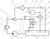 |
Fig. 1. Modernized hydraulic system of an agricultural tractor (description is in the text) |
2.2 Centrifuge research methodology
A hydraulic bench is proposed to be used as a means of evaluating the centrifuge efficiency (Fig. 2). It includes an oil tank 1, a gear pump 2, an electric motor 3, a throttle-flowmeter 4, a centrifuge 5, an additive dispenser 6, pressure gauges 7 and 8, cranes 9 ... 13, a meter for measuring the rotational speed of the pump shaft 14, a non-contact tachometer 15, a liquid purity control device 16, an electric mixer 17, a heater 18 for heating oil in the tank 1, and a capillary thermostat 19. Application of the taps 9 and 13 enables to take samples of the working fluid before and after the centrifuge. The heating temperature of the vegetable-mineral lubricant composition is maintained by means of a capillary thermostat 19.
A vegetable-mineral lubricant composition (25 l) is poured into the tank 1 and pumped by a gear pump 2. The pump 2 is driven by an electric motor 3. The pump shaft speed can vary between 170 ... 2000 min–1. The working fluid along the discharge line is fed to a centrifuge 5 and then to the drain. The pressure before and after the centrifuge is regulated by valves 9, 10 and 11, the measurement is carried out by pressure gauges 7 and 8. The power fluid in tank 1 is heated by an electric heating tube 18 to a temperature of 60 ± 5°C and mixed with an electric mixer 17. Additive batcher 6 carries out targeted alloying of the working fluid with colloidal graphite.
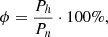
The completeness and subtlety of screening pollutant particles of various fractions are taken as the compared indicators. The completeness of screening φ was determined by the following formula:
 (1)
(1)
where Рh is mass of contaminants held by a centrifuge, g; Рn is mass of contaminants introduced into the working fluid 7.
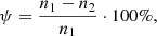
Screening fineness was estimated by the screen fineness coefficient ψ:
 (2)
(2)
where n1 are the particles of this size group in unfiltered oil, pcs; n2 are particles of this size group in purified oil, pcs.
Microscopic analysis was carried out on the microscope MBI-6.
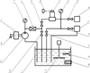 |
Fig. 2. Schematic diagram of a hydraulic stand for evaluating oil filters performance (description is in the text) |
2.3 Experimental procedure
A centrifuge with a rotor height of H=137 mm and a rotor diameter of d=148 mm was tested [10]. The centrifuge rotory speed was 5,000±50 min–1, the pressure of the vegetable-mineral lubricant composition at the inlet of the centrifuge was 0.45 MPa. The flow rate of the working fluid through the centrifuge under these conditions was 30 l/min. Quartz dust with a specific surface of 10.500 cm2/g was used as a pollutant (Table 1). Previously, the working fluid was contaminated to a concentration of silica dust of 0.1 % by mass, and then 5 more quartz dust was introduced into the tank 1 every 30 min.
The screening completeness φ and the screen fineness coefficient ψ screening for the size groups of contaminant particles were taken as centrifuge efficiency. The measurements were carried out by means of microscopic analysis, then the results were statically processed, and the obtained values of screening completeness and a screening fineness coefficient were used to plot the changes in the main centrifuge indicators depending on the cleaning time as well as screening fineness coefficient on the particle diameter of the contaminants.
Quartz dust characteristic
2.4 Performance test procedure
The modernized tractor hydraulic hitch system performance using a vegetable-mineral lubricant composition as the power fluid was assessed in the hydraulic hinged systems of universal cultivating tractors MTZ-1221. A tractor with a serial hydraulic system was indicated as number one, a tractor equipped with an upgraded hydraulic system was indicated as number two. Operational tests were carried out in the conditions of agricultural enterprises of the Samara region. The level of the hydraulic system units wear was determined by the content of metal wear products in the power fluid. Sampling was carried out every 100 hours of work. The sample volume is 10 ... 50 ml. The concentration of iron in the samples was determined by the photocolorimetric method using a photocolorimeter KFK-2. Further, statistical processing of the results was carried out, and graphical dependences of iron particles concentration in the power fluid on the operating time of the tractors were also constructed.
3 Research results
Graphical dependences of the change in the main centrifuge indicators during cleaning are shown in Figure 3. The analysis results make it clear that without applying a centrifugal cleaning unit (line 1) the solids concentration in the power fluid increases, and after 150 minutes the hydraulic system operation increases from 0.1 to 0.2 %. When using the centrifugal cleaning unit (line 3) for 60 min of operation of the hydraulic system, the concentration of solids decreases from 0.1 to %. When using the centrifugal cleaning unit (line 3) for 60 min, the concentration of solids decreases from 0.1 to 0.02 %.
A further increase in the concentration of mechanical impurities is associated with the peculiarity of the experiment, which involves adding 5 g of silica dust to the tank with a working fluid every 30 minutes of the stand operation. The efficiency of the centrifugal cleaning unit is confirmed by the nature of curve 3, according to which the initial permissible concentration of abrasive particles is achieved only after 270 minutes of stand operation.
The graphical dependence of the screening fineness coefficient on the contaminants particle diameter is shown in Figure 4.
The graphical dependence shown in Figure 4 demonstrates that the coefficient of screening fineness for the most dangerous components of the hydraulic system being the particles with a diameter of 8 ... 15 μm, capable of causing abrasive wear is within 78 ... 83 %, which indicates the ability of a centrifuge with specified parameters (rotor with H=137 mm, diameter of d=148 mm, speed of 5000±50 min–1) to provide the necessary quality for cleaning the working fluid from mechanical impurities.
Graphic dependences of changes in the concentration of iron in the power fluid on the tractors operating time are presented in Figure 5.
A dependency analysis presented in Figure 5 shows that in the power fluid of the standard hydraulic system of tractor No. 1, the concentration of Fe during the operational test period changed from 0 to 0.0092 %, while this indicator for the modernized hydraulic system of tractor No. 2, which uses the quality of the working fluid of the vegetable-mineral lubricant composition amounted to 0.004 % at the end of the operational test period.
Operational test results show that the use of a centrifugal cleaning unit and a vegetable-mineral lubricant composition doped with colloidal graphite in a hydraulic system allows to reduce the amount of wear products in the working fluid by 2.3 times with an average tractor operating time of 1,200 motohours.
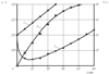 |
Fig. 3. Change in the main indicators of the centrifuge depending on the cleaning time: 1 is concentration of impurities in the RSMK (cleaning was not performed); 2 is a change in dropout rate; 3 is the concentration during continuous operation of the centrifuge |
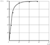 |
Fig. 4. Dependence of the coefficient of screening fineness on the diameter of the contaminants particles |
 |
Fig. 5. Change in the concentration of Fe in the power fluid depending on the operating time |
4 Conclusion
It follows from the analysis of graphical dependences obtained experimentally that a centrifuge with specified parameters (rotor with H=137 mm, diameter of d=148 mm, speed of 5000±50 min-1) provides the necessary quality for cleaning the working fluid from mechanical impurities. Studies have also shown that the use of a modernized hydraulic system with a vegetable-mineral lubricant composition as a power fluid can reduce the wear of the parts of hydraulic system units by 2.3 times. Thus, it can be argued that the proposed modernized hydraulic system adapted for being used as a power fluid of a vegetable-mineral lubricant composition (88.9 % rape oil, 3.7 % additive DF-11, 3.2 % additive ETF, % PMS-200A and 4.197 % colloidal graphite), is effective and recommended for being applied in agricultural tractors.
References
- A. Sharafian, P. Blomerus, W. Merida, Natural gas as a ship fuel: Assessment of greenhouse gas and air pollutant reduction potential, Energy Policy 131, 332–346 (August 2019) [CrossRef] [Google Scholar]
- K.P. Laberteaux, K. Hamza, A study on opportune reduction in greenhouse gas emissions via adoption of electric drive vehicles in light duty vehicle fleets, Transportat. Res. Part D: Transp. and Environment 63, 839–854 (August 2018) [CrossRef] [Google Scholar]
- S. Hänggi, P. Elbert, T. Bütler et al., A review of synthetic fuels for passenger vehicles, Energy Reports 5, 555–569 (November 2019) [CrossRef] [Google Scholar]
- D.A. Ukhanova, S.Yu. Dmitrieva, D.A. Ukhanov, A.P. Ukhanov, Flaxseed oil is a promising bioadditive to diesel engine fuel, Volga Niva 1(46), 121–127 (2018) [Google Scholar]
- D. Kurczynski, P. Lagowski, Performance indices of a common rail-system CI engine powered by diesel oil and biofuel blends, J. Energy Instit. 92, 1897–1913 (2018) [CrossRef] [Google Scholar]
- S. Omar, S. Alsamaq, Y. Yang, J.W. Wang, Production of renewable fuels by blending bio-oil with alcohols and upgrading under supercritical conditions, Frontiers of Chem. Sci. and Engineer. 13, 702–717 (2019) [CrossRef] [Google Scholar]
- J.K. Mannekote, S.V. Kailas, K. Venkatesh, N. Kathyayini, Environmentally friendly functional fluids from renewable and sustainable sources, Renewable & sustainable energy reviews 81, 1787–1801 (January 2018) [CrossRef] [Google Scholar]
- M.P. Schneider, Plant-oil-based lubricants and hydraulic fluids, J. of the sci. of food and agricult. 86, 1769–1780 (September 2006) [CrossRef] [Google Scholar]
- O.S. Volodko, A.P. Bychenin, D.N. Bazhutov, Vegetable-mineral lubricant composition for hydraulic systems, Rural machine operator 6, 30–31 (2019) [Google Scholar]
- D.N. Bazhutov, O.S. Volodko, Analytical justification of the dimensional parameters of the rotor of a centrifugal cleaner, in: Mechanization and automation of construction. Digest of articles pp. 91–95 (Samara State Techn. Univer., Samara, 2016) [Google Scholar]
All Tables
All Figures
|
Fig. 1. Modernized hydraulic system of an agricultural tractor (description is in the text) |
| In the text | |
|
Fig. 2. Schematic diagram of a hydraulic stand for evaluating oil filters performance (description is in the text) |
| In the text | |
|
Fig. 3. Change in the main indicators of the centrifuge depending on the cleaning time: 1 is concentration of impurities in the RSMK (cleaning was not performed); 2 is a change in dropout rate; 3 is the concentration during continuous operation of the centrifuge |
| In the text | |
|
Fig. 4. Dependence of the coefficient of screening fineness on the diameter of the contaminants particles |
| In the text | |
|
Fig. 5. Change in the concentration of Fe in the power fluid depending on the operating time |
| In the text | |
Current usage metrics show cumulative count of Article Views (full-text article views including HTML views, PDF and ePub downloads, according to the available data) and Abstracts Views on Vision4Press platform.
Data correspond to usage on the plateform after 2015. The current usage metrics is available 48-96 hours after online publication and is updated daily on week days.
Initial download of the metrics may take a while.