| Issue |
BIO Web Conf.
Volume 17, 2020
International Scientific-Practical Conference “Agriculture and Food Security: Technology, Innovation, Markets, Human Resources” (FIES 2019)
|
|
|---|---|---|
| Article Number | 00018 | |
| Number of page(s) | 6 | |
| DOI | https://doi.org/10.1051/bioconf/20201700018 | |
| Published online | 28 February 2020 | |
On the issue of the installation of the purification degree dependence of polluted spent mineral oil on the hydrocyclone constructive and geometrical parameters
1
Ulyanovsk State Agrarian University named after P.A. Stolypin, 432017 Ulyanovsk, Russia
2
Kazan State Agrarian University, 420015 Kazan, the Republic of Tatarstan, Russia
* Corresponding author: This email address is being protected from spambots. You need JavaScript enabled to view it.
Abstract
The urgency of the issue is reasoned by the necessity to develop environmentally friendly technologies and engineering tools for cleaning emerged mineral oil from insoluble impurities in order to reuse them in the nodes and auto-tractor equipment systems. Hydrocyclone is one of the simplest and most effective means of cleaning waste oil. In order to determine the possibility of hydrocyclone usage in technological lines for purifying oils, it is necessary to establish the influence of its geometrical parameters on the purification quality of such high-viscosity liquid as emerged mineral oils. The purpose of the article is to study theoretically the cylindro-conical hydrocyclone geometrical parameters influence on the purification degree of emerged high-viscosity mineral oils from insoluble and wear debris. The leading approach to the study of this problem is the consideration of the behavior of a non-soluble particle in an oil stream under the influence of forces acting on it, which allows identifying the geometric and regime parameters of a cylindro-conical hydrocyclon. These parameters have the greatest influence on the oil purification degree. The article presents a theoretical justification for the geometrical parameters influence of a cylindrical-conical hydrocyclone on the emerged oil purification degree, a separation criterion, which allows not only determining the optimal size of a hydrocyclone, but also conducting a comparative assessment of hydrocyclones with different geometric parameters by oil purification efficiency from insolubles. Theoretical researches are aimed at determining the cylindro-conical hydrocyclone geometric parameters, depending on the pollution intensity of the emerged mineral oil and the desired degree of its purification from insolubles.
© The Authors, published by EDP Sciences, 2020
 This is an Open Access article distributed under the terms of the Creative Commons Attribution License 4.0, which permits unrestricted use, distribution, and reproduction in any medium, provided the original work is properly cited.
1 Introduction
The principle of oils and various technical fluids of purification and drying in force fields remains one of the most common. Various kinds of centrifuges and separators are widely used for this purpose. The principal disadvantage of all centrifuges and separators is the quality deterioration of oil purification at its lowering temperature, the devices complexity and low reliability [1, 2].
Recently, hydrocyclone units have been increasingly used for the various liquids purification, where solid particles are released from the purified oil stream under the influence of centrifugal forces. Hydrocyclone units are more reliable because they have no rotating parts, low cost, and easy maintenance. They can be installed in various places without perpendicular [3, 4]. Nowadays, many research centers are working on the hydrocyclone units’ use for the various liquids purification.
A hydrocyclone (Fig. 1) is an apparatus consisting of a cylindrical part 1, to which a conical part 7 adjoins the bottom with a wide base, and an intermediate drain chamber 3 with a branch pipe for discharging the top product. The diaphragm 6 is installed between the cylindrical part and the drain chamber, and replaceable nozzles 8 are fixed in the lower part of the cone.
Hydrocyclone for the purification of the emerged motor oil works as follows. Polluted oil under pressure enters through a device for admission 3 of cleaning oil tangentially into the cylindrical part of the body 1 and, acquiring a rotational motion, moves into the conical part of the body 1. This causes significant centrifugal forces exceeding gravity.
The heavier fractions of the purified oil under centrifugal forces move from the hydrocyclone axis to the walls of its body 1 in a spiral trajectory downward. Then the heavy fractions are removed from the hydrocyclone through the drain pipe 7. The lighter fractions move in the inner spiral flow, directed upwards, inside the diaphragm 2. Then they enter to the internal part of the lid 5 and are removed through the device for draining cleaned oil 4 outside.
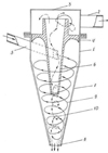 |
Fig. 1. Hydrocyclone diagram (explanations are in the text) |
2 Particle settling diameter determination
2.1 Theoretical investigations
The separation process of emerged oils into fractions in a hydrocyclone can be represented as follows. The following forces act on a particle that is in a fluid flow in a hydrocyclone (fig. 2): the centrifugal force Pz, throwing the particle to the periphery; the radial force Pr, arising the particle from the action of the radial fluid flow and directed to the apparatus axis; Coriolis force Pk, which moves a particle in a circumferential direction relative to the flow; the resistance force of the environment Pc, preventing the particle settling deposition; inertial force Pu, which appears as a result of a particle settling speed change.
If the particle is small and carries along by the flow into rotational motion with an angular velocity ω, then the main force acting on it is centrifugal one (Shestov, 1967) (1)
(1)
where m – is the particle mass, kg; ω – is the angular velocity of rotation, s−1; r – is the particle rotation radius, m; δ – is the particle diameter, m; ρ – is the particle density, kg/m3; v – is the linear local flow velocity, m/s.
We can observe the Stock-Soviet (laminar) mode of particles sedimentation in the oil flow, ensuring their separation into phases by a spiral-like movement of the fluid flow in a hydrocyclone. If we take into account the centrifugal force Rz action and the medium resistance force Pc, then from expression (1) with consideration for the medium resistance force, we get: (2)
(2)
where ρl is the liquid density, kg/m3; vs – is the separation rate (solid particles of insoluble impurities release from the oil), m/c; μ is the kinematic viscosity of the oil being cleaned, m2/s.
Then (3)
(3)
The inertial force Pu is due to a change in the relative particle velocity in the medium flow when the particle velocity profile is rearranged at the entrance to the cylindrical part of the hydrocyclone. The fluid flow enters the cyclone with the initial velocity vH (the fluid velocity in the inlet nozzle of the cyclone); then the velocity profile changes along line 1-1 (Fig. 2). The velocity profile vH (Fig. 2. line 2-2) is changed by a fluid transition into a curving duct of the inlet nozzle and its distribution over the inlet channel cross section corresponds to the law (Shestov, 1967) of variation the tangential velocity from radius. (4)
(4)
where n is a freedom indicator.
Then the fluid velocity distribution in the curvilinear channel (line 2–2 in Figure 2) will be determined by the dependence: (5)
(5)
where R2 is the fluid flow outer radius, equal to the hydrocyclone radius R2 = Rz, m; R1 is the fluid flow internal radius in a hydrocyclone, m
Substituting (5) in (3) we get: (6)
(6)
Taking as a current radius r its average value: (7)
(7)
We get a generalized dependence characterizing the minimum diameter of the deposited particles: (8)
(8)
where D is cyclone diameter D=2R2, m
However, the use of the average value radius allows determining only the particles diameter locating at a given radius, and does not allow obtaining the real diameter of the deposited particle. To solve this problem, it is necessary to use the radius value of zero vertical velocity. If we assume that there is no vertical effect on the particle in the cyclone flow, then each particle will be suspended at a certain distance from the center of rotation, that is, at a distance where the centrifugal force will be equal to the radial force Pz = Pr.
Heavier particles will be located closer to the hydrocyclone periphery, and light ones will be located at its center. Each group of particles in the oil flow in the inner conical hydrocyclone cavity will create a curved-linear surface (Fig. 3) when they are moving.
Zero vertical velocity points (that is, the boundaries of the vertical velocity signs change) also create a curved surface. The intersection or coincidence of the vertical velocity plane with the plane of any group particles will give the value of the boundary grain, with the larger grain going to the drain and the smaller grain to the cleaned stream.
It is necessary to determine the axial velocity of a particle moving in a hydrocyclone flow to define the radius of the zero surface.
We use the formula to calculate the axial velocity [4]:![Mathematical equation: $$ \begin{aligned}{\upsilon _z} = \frac{G}{{4\pi \cos \frac{{{\alpha _1}}}{2}}}\int\limits_0^{H + {H_1}} {dh\int\limits_0^{2\pi } {\frac{{\left( {{R_0} - htg\frac{{{\alpha _1}}}{2}} \right)}}{{\left[ {{{\left( {h - z} \right)}^2} + {{\left( {{R_0} - htg\frac{{{\alpha _1}}}{2}} \right)}^2}} \right.}}} }\cr \frac{{ - \left( {{R_0} - htg\frac{{{\alpha _1}}}{2}} \right)R\cos \beta }}{{{{\left. { + {R^2} - 2R\cos \beta \left( {{R_0} - htg\frac{{{\alpha _1}}}{2}} \right)} \right]}^{{3/2}}}}}d\beta, \end{aligned} $$](/articles/bioconf/full_html/2020/01/bioconf_fies2020_00018/bioconf_fies2020_00018-eq9.gif) (9)
(9)
where G=const is the velocity circulation per unit of the toroid height (10)
(10)
Ro is the surface radius of zero axial velocities at the boundary of the cylindrical and conical parts of the hydrocyclone, m (11)
(11)
where RΓ is the radius of the hydrocyclone, m; ro is the radius of the air column (ro = 0,606rc), m; rc is the radius of cleaned oil discharging, m; rn is the radius of the drain pipe, m; α1 is the taper angle of the hydrocyclone, deg.; β is the angle of inclination or the offset angle of a point when moving in a vortex layer to a height (h-z), deg.; h is the distance of the considered annular section from the beginning of the vortex layer (i.e, from the top lid of the hydrocyclone cylindrical part), m; H is the height of the hydrocyclone conical part, m; H1 is the height of the hydrocyclone cylindrical part, m.
Tangential velocity of the particle![Mathematical equation: $$ \begin{gathered}{\upsilon _t} = C \cdot {r_0}\int\limits_0^{H + {H_1}} {dh\int\limits_0^{2\pi } {\frac{R}{{\left[ {{{\left( {h - z} \right)}^2} + {r_n} + {R^2} - 2{r_n}\cos \beta } \right]}}} } \hfill \\ \frac{{ - {r_n}\cos \beta }}{{\left( {r_n^2 + {R^2} - 2{R_0}\cos \beta } \right)}}d\beta, \end{gathered} $$](/articles/bioconf/full_html/2020/01/bioconf_fies2020_00018/bioconf_fies2020_00018-eq12.gif) (12)
(12)
where C is a constant value characterizing the dependence of productivity on the hydrocyclone height; rH is the outer diameter of the considered annular section, m; R and z are the coordinates of the point for which the velocity is determined, m; vt — tangential velocity of the particle, m/s; dh is the height of the considered ring, m; (13)
(13)
Axial velocity of a particle![Mathematical equation: $$ \begin{gathered}{\upsilon _z} = \frac{{2\pi rC{r_0}}}{{4\pi \cos \frac{{{\alpha _1}}}{2}}}\int\limits_0^{H + {H_1}} {\int\limits_0^{2\pi } {\frac{R}{{\left[ {{{\left( {h - z} \right)}^2} + {r_n} + {R^2} - 2{r_n}\cos \beta } \right]}}} } \hfill \\ \frac{{ - {r_0}\cos \beta }}{{\left( {r_0^2 + {R^2} - 2{R_0}\cos \beta } \right)}} \times \hfill \\ \times \int\limits_0^{H + {H_1}} {dh\int\limits_0^{2\pi } {\frac{{\left[ {{{\left( {{R_0} - htg\frac{{{\alpha _1}}}{2}} \right)}^2}} \right.}}{{\left[ {{{\left( {h - z} \right)}^2} + \left( {{R_0} - htg\frac{{{\alpha _1}}}{2}} \right)} \right.}}} } \hfill \\ \frac{{\left. { - \left( {{R_0} - htg\frac{{{\alpha _1}}}{2}} \right)R\cos \beta } \right]}}{{{{\left. { + {R^2} - 2R\cos \beta \left( {{R_0} - htg\frac{{{\alpha _1}}}{2}} \right)} \right]}^{\frac{3}{2}}}}}d\beta dh \hfill \\ \end{gathered} $$](/articles/bioconf/full_html/2020/01/bioconf_fies2020_00018/bioconf_fies2020_00018-eq14.gif) (14)
(14)
In order to establish a criterial form communication in the form of a regression model of the zero surface radius dependence Ro on the hydrocyclone parameters, we compose a matrix, taking as predictors: the height of the hydrocyclone working part H+H1, the particle coordinate according to the hydrocyclone radius R, the particle coordinate according to the hydrocyclone height H+H1, distance to the considered section h of the hydrocyclone conical part, diameter of the section d, axial velocity vz (Table 1).
The regression equation will be (15)
(15)
where ao, a1,...aп are regression coefficients with selected parameters of a hydrocyclone; X1, X2, … Xn are the parameters of the hydrocyclone.
Having preliminary information about the influence of the hydrocyclone listed parameters on the radius of the surface of zero axial velocity, we present the functional dependence in general form (16)
(16)
To calculate the coefficients, we determine the change in the axial velocity and the coordinates of a particle moving in a vortex flow of a hydrocyclone at three points of the section along the height and ten points along the radius of the hydrocyclone [5, 6, 7]. In this case, the particle coordinate z will take certain numerical values depending on the diameter of the section, and accordingly, on its position along the height of the hydrocyclone. Given the condition that the z coordinate is a numerical variable value, we will get:
 (17)
(17)
that is, only the coordinate of the point being examined will change R. After calculating the position of the point, we will obtain a series of numerical values of the main parameters.
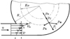 |
Fig. 2. Forces, acting on a particle in a spiral flow in a hydrocyclone |
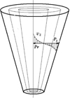 |
Fig. 3. Diagram of particle surfaces in a hydrocyclone flow |
Matrix for the establishment of communication in the criterial form
3 Research results
A quadratic equation of the axial velocity of the particle in the flow is obtained after determining the coordinates of changing the position of a particle in a hydrocyclone flow and calculating the regression coefficients. After substituting into it the boundary values of the predictors defined for these specific conditions (h = 0,01–0,18 m, R0 = 0,02 m, ro = 0,017 m, α = 5o2′, H+Ho = 0,302 m, β = 100–1200, R = 0,018–0,046 m), and transformations, a theoretical dependence of the axial velocity of a particle in a flow, on the design and technological parameters of a hydrocyclone depending on the required values of the quality of oil cleaning is obtained. (18)
(18)
For the calculations of the boundary layer radius (zero surface), the dependence of the hydrocyclone parameters is obtained: radius R, height (as a function of performance) C on the particle coordinate in the cleaning flow z: (19)
(19)
Substitute zero surface radius equation (17) of the axial velocity in expression (6), replacing the value of the diameter of the hydrocyclone D by the radius of the zero surface 2Ro. Then we will get the size of the particles separated at a certain radius of the cyclone: (20)
(20)
The obtained dependence clearly shows the relationship of each quantity in the radicand with the size of the particles separated in the spiral flow of the hydrocyclone. At the same time, the size of separated particles will increase with the increase in the radius of the zero surface. Therefore, reduced diameters hydrocyclones should be used to trap fine particles [5, 6]. Increasing of the initial flow velocity of the cleaned oil vH (in the cyclone inlet) also contributes to the separation of smaller particles.
The using of expression (18) to determine the minimum size of a detachable particle for practical purposes is not always possible, since it contains an unknown quantity — the separation velocity vc.
To determine the separation velocity, we assume that the particle entering the cyclone near the inlet nozzle (radius R1) must settle on the wall of the cyclone during its passing through the cylindrical-conical part of the cyclone. (21)
(21)
where Vh is the volume of the hydrocyclone cylindrical-conical part, m3; Qh is the hydrocyclone productivity, m3/h; H is the height of the hydrocyclone cylindrical-conical part, m.
Whereas the separation of particles occurs at radius Ro, replacing R2-R1 with Ro, we get (22)
(22)
In this case, the particle settling rate (23)
(23)
Three quantities are essential for separation of a particle in a hydrocyclone: the separation rate vc, the thickness of the deposition layer and the residence time of the particle in the hydrocyclone τ.
A parameter can be made up of these three quantities – a separation criterion that determines the amount of particles to be separated from the purified oil stream. (24)
(24)
where λ is the thickness of the deposition layer, m.
Since the thickness of the deposition layer is determined by the boundary values of the radii Rz – Ro, then (25)
(25)
Since the quality of cleaning determines the amount of deposited impurities, we replace the volume of supplied oil with the amount of impurities in the cleaned oil. Performing the replacement and substituting the value of vc in the formula (22), we get (26)
(26)
where Gh is the amount of impurities in the cleaned oil, kg.
In this case, the quality of hydrocyclone cleaning can be defined as the particles entrainment through a drain hole, expressed as a percentage of the particles total number entering the hydrocyclone with the cleaned oil: (27)
(27)
Thus, the quality of oil purification will be determined by the geometrical parameters of the hydrocyclone and the residence time of the particle in the hydrocyclone, depending on the separation mode.
The comparative laboratory studies of the efficiency of purification of spent mineral oil from insoluble impurities using experimental and controlling hydrocyclones were carried out to confirm the obtained theoretical calculations. A hydrocyclone made according to the calculating method of its geometrical parameters recommended by most researchers was used as a controlling [8–10].
In the process of research, it was found that an experimental cylindro-conical hydrocyclone, with geometrical parameters set in accordance with the theoretical calculations, provides the best degree of purification (88.4%) with a process productivity of 3...5 t/h, input flow pressure P = 0.04 MPa and the diaphragm seal immersion depth of a hydrocyclone H = 136.8 mm, contrary to 21.6% for a typical hydrocyclone.
4 Conclusion
The purification degree of oil from insoluble impurities will be determined by the geometrical parameters of the hydrocyclone: radius Rz, the height of the cylindrical-conical part H and the time the particle stays in the hydrocyclone, depending on the separation mode. The results of the comparative laboratory studies show that the calculations of the structural and technological parameters of the hydrocyclone according to the proposed method provides a higher degree of purification of spent mineral oils from insoluble impurities.
References
- A.A. Glushchenko, D.E. Molochnikov, S.A. Yakovlev, I.N. Gayaziev, To the issue of purification of spent oils from insoluble impurities in a hydrocyclone Vestnik of Kazan state agrarian Univer. 3(50), 81–84 (2018) [Google Scholar]
- K.U. Safarov, V.M. Kholmanov, M.M. Zamaldinov, Restoration of motor oils by the step method Vestnik of Ulyanovsk state agricultural Academy 3, 84–87 (2000) [Google Scholar]
- S.A. Kolokoltsev, M.M. Zamaldinov, Changing the quality of engine oil during operation of an internal combustion engine Sci. in Central Russia. Tambov 4S, 38–40 (2013) [Google Scholar]
- E.S. Zamaldinov, K.U. Zykin, Filter for cleaning used engine oil Patent for utility model RUS no. 107704 (26 April 2011) [Google Scholar]
- M.M. Zamaldinov, Removal of mechanical impurities and water from used engine oil by gravity sedimentation method in Interuniversity collection of sci. papers of the XVI Region Sci. and Pract. Conf. of Univer. of the Volga and Ural Regions “Improving the use of automotive and agricultural machinery”, ed. V.D. Korotnev, 170–173 (Penza, State Agricultural Academy, 2005) [Google Scholar]
- K.U. Safarov, M.M. Zamaldinov, Problems of the petroleum products secondary use at the present stage in Mat. of the Russian national Sci. and Pract. Conf. “Modern Development of the AIC: Regional Experience, Problems, Prospects”, eds. V.G. Artemyev, A.Kh. Kulikova, V.M. Kholmanov, 260–261 (Ulyanovsk, State Agricultural Academy, 2005) [Google Scholar]
- V.M. Kholmanov, M.M. Zamaldinov, Determination of the hydrocyclone optimal operating mode in Mat. of the Russian national Sci. and Pract. Conf. “Modern Development of the AIC: Regional Experience, Problems, Prospects”, eds. V.G. Artemyev, A.Kh. Kulikova, V.M. Kholmanov, 261–263 (Ulyanovsk: State Agricultural Academy, 2005) [Google Scholar]
- K.U. Safarov, V.M. Kholmanov, M.M. Zamaldinov, The study of improving the motor oils quality Bull. of the Ulyanovsk State Agricultural Acad. 3, 65–67 (State Agricultural Academy, Ulyanovsk, 2000) [Google Scholar]
- A.N. Zazulya, A.A. Glushchenko, D.E. Molochnikov, M.A. Karpenko, G.V. Karpenko, Theoretical substantiation of the cylindrical-conical hydrocyclone geometric parameters influence on the degree of waste lubricating purification oils from insoluble impurities Sci. in Central Russia 2(38), 116–123 (2019) [Google Scholar]
- M.M. Zamaldinov, K.U. Safarov, S.A. Kolokoltsev, The regeneration of spent mineral motor oils by centrifugation in Collec. of articles of the Russian national sci.-pract. Conf. “Operation of automotive machinery: experience, problems, innovations, prospects” 39–42 (State Agricultural Academy, Ulyanovsk, 2013) [Google Scholar]
All Tables
All Figures
|
Fig. 1. Hydrocyclone diagram (explanations are in the text) |
| In the text | |
|
Fig. 2. Forces, acting on a particle in a spiral flow in a hydrocyclone |
| In the text | |
|
Fig. 3. Diagram of particle surfaces in a hydrocyclone flow |
| In the text | |
Current usage metrics show cumulative count of Article Views (full-text article views including HTML views, PDF and ePub downloads, according to the available data) and Abstracts Views on Vision4Press platform.
Data correspond to usage on the plateform after 2015. The current usage metrics is available 48-96 hours after online publication and is updated daily on week days.
Initial download of the metrics may take a while.