Fig. 4.
Download original image
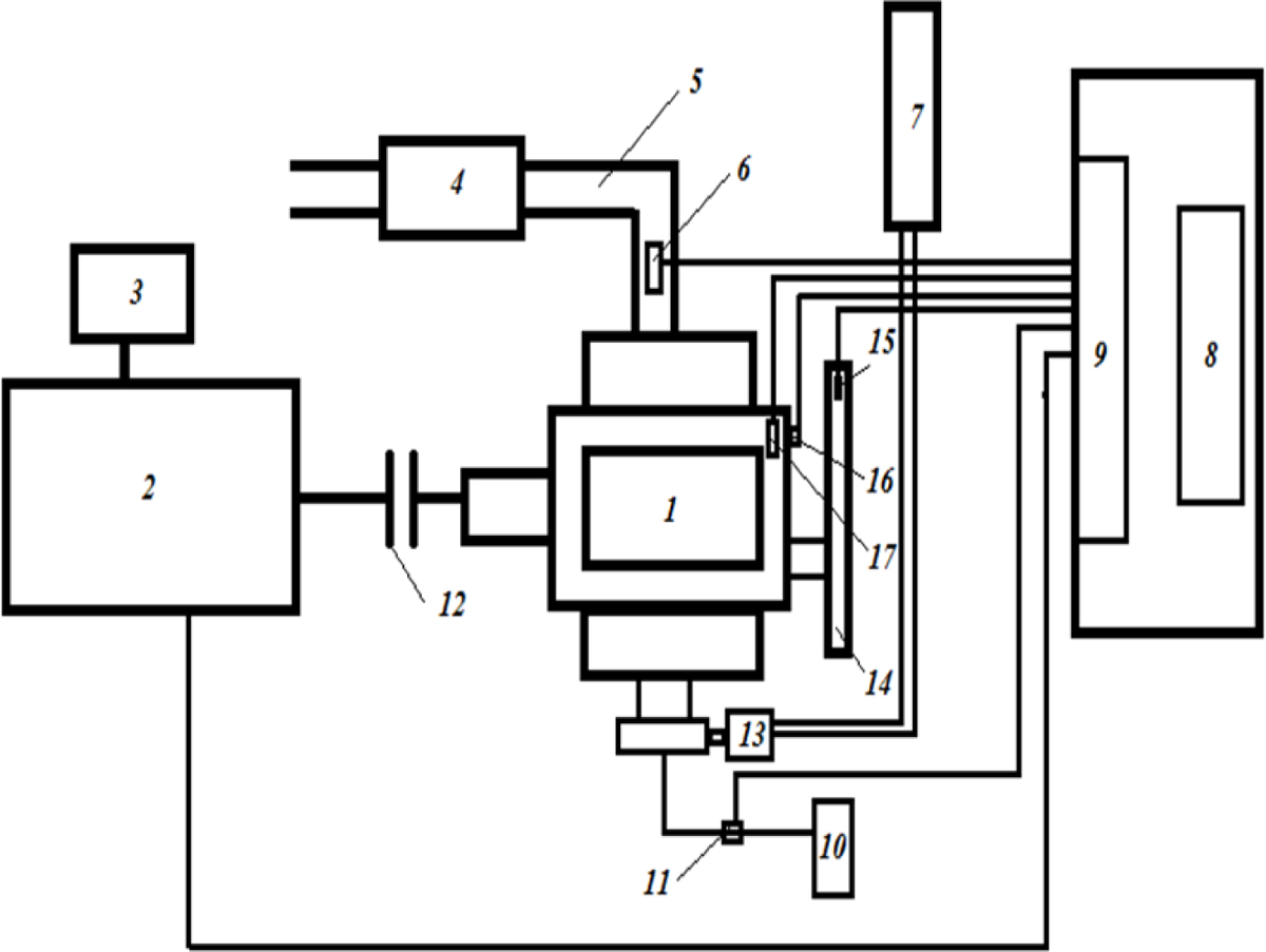
Structural diagram of the brake stand: 1 – internal combustion engine; 2 – engine test bench; 3 – balance dynamometer; 4 – silencer; 5 – exhaust system; 6 – gas analyzer; 7 – receiver for air; 8 – control panel; 9 – instrument panel from sensors on the engine; 10 – fuel tank; 11- device for measuring fuel consumption; 12 – engine coupling with a stand; 13 – air filter; 14 – water cooling system; 15 – temperature gauge of the engine cooling system; 16 – engine oil pressure gauge; 17 – electronic tachometer
Current usage metrics show cumulative count of Article Views (full-text article views including HTML views, PDF and ePub downloads, according to the available data) and Abstracts Views on Vision4Press platform.
Data correspond to usage on the plateform after 2015. The current usage metrics is available 48-96 hours after online publication and is updated daily on week days.
Initial download of the metrics may take a while.