| Issue |
BIO Web Conf.
Volume 17, 2020
International Scientific-Practical Conference “Agriculture and Food Security: Technology, Innovation, Markets, Human Resources” (FIES 2019)
|
|
|---|---|---|
| Article Number | 00093 | |
| Number of page(s) | 5 | |
| DOI | https://doi.org/10.1051/bioconf/20201700093 | |
| Published online | 28 February 2020 | |
Mathematical modeling of the grain trajectory in the workspace of the sheller with rotating decks
Kazan State Agrarian University, 420015 Kazan, Russia
* Corresponding author: This email address is being protected from spambots. You need JavaScript enabled to view it.
Abstract
The purpose of the work is to determine the possibility of controlling the operation of cereal grain husks by changing the angular rotation speed of the disk (rotor) and deck to provide optimal conditions for peeling (removal of the flower shell from the grain). For this purpose, the movement of grain in the working space of the husk between the disk and the rotating deck is considered. The mathematical model of grain movement in the working space of the husk, taking into account the real aerodynamics of the rotating air flow, where the efficiency of peeling is determined by the speed and direction of the grain flight, is presented. To study the nature of the influence of structural and regime parameters of the desiccant on the efficiency of work, on the basis of the obtained mathematical model, numerical calculations and graphical dependences are made. On the basis of the analysis of the received graphs it is revealed that the direction of the grain impact on the deck is strongly influenced by the direction of the grain velocity vector at the moment of its tearing from the disk edge and the deck rotation angle speed. At the same time, the right angle impact of the grain can be achieved at low speeds of the deck rotation, and the speed of the grain during the impact is mainly determined by the speed of the disk rotation and practically does not depend on the speed of the deck rotation.
© The Authors, published by EDP Sciences, 2020
 This is an Open Access article distributed under the terms of the Creative Commons Attribution License 4.0, which permits unrestricted use, distribution, and reproduction in any medium, provided the original work is properly cited.
1 Introduction
At the present stage of development of agro-industrial complex, characterized by constant improvement of technologies and technical means of production and processing of crop and livestock products, the task of processing of competitive, agricultural crops the final product directly at the places of their production is more urgent than ever before. [1].
When processing cereal grains into cereals, an important technological operation that determines the quality of products is peeling – separation of the outer shells of grain from the core.
There are a lot of machines for this operation, which differ from each other both in the way of influence on the processed product, and in the design features of the working bodies. One of these machines is a sheller with a rotating deck [2].
The main working organ of the sheller with the rotating deck is the paddle disc (rotor), which rotates inside a closed cylindrical surface (deck). The rotating paddle disc is fed with the grain material, accelerated and ejected towards the deck, which is flaked on impact (Fig. 1). The deck may be stationary or may have a reverse rotation around the paddle plate.
Theoretical studies of grain movement along the vane disk and interaction with fixed working surfaces (decks) are studied and shown in [3–8].
However, in the case of a peeler with a rotating deck, the movement of grain after separation from the paddle disk is of a special nature and has not been studied sufficiently. The efficiency of peeling here is determined to a greater extent by the speed and direction of grain flight at the moment of its collision with the deck wall, which in turn depends on the speed of rotation of the disk and deck.
Therefore, in order to choose the optimal design and technological parameters of the desiccant it is necessary to know the mathematical model of grain movement, taking into account the real aerodynamics of the rotating air flow.
 |
Fig. 1. Sheller scheme with rotating deck: 1 – paddle plate (rotor); 2 – deck. |
2 Materials and methods
The free flight of grain after it has been stripped off the disc can be considered horizontal because of its high speed and small working area. The downward deposition of grain under gravity and air flow forces is not significant, and its impact on flight time and peeling efficiency can be neglected. Then the mathematical model of grain movement can be constructed in two-dimensional form.
The air flow between the rotating rotor and the deck is axisymmetrical and stationary. Despite the small distance between the rotating parts, the flow is three-dimensional in nature. Near the rotor, the rotational-radial flow of air prevails, and near the deck, it becomes the rotational-axial flow. The aerodynamic characteristics of the flow are influenced by both the operating conditions and design features of the installation. Moreover, the features of the upper part of the deck, as well as the angle of inclination of the deck forming it, can greatly affect the picture of the current.
Therefore, the calculation of the real aerodynamic situation is possible when solving the Navier-Stokes equations in a three-dimensional formulation, which causes great difficulties. In this paper, on the basis of the model representation of the air flow, changes in the grain velocity and its direction under the influence of the opposite direction of air flow generated by the reversible deck are investigated.
The deck design visibly limits the airflow into the working area of the unit. Therefore, it can be assumed that between the rotor and the deck, the tangential component of the flow rate prevails over the other components. Then the tangential component of the flow velocity can be described by the ratio [2]: (1)
(1)
where r – current radius (coordinate), m; R1 – disk radius, m; R2 – deck radius, m.; ω1 – disk angular velocity, c−1; ω2 – deck angle speed, c−1.
Since the rotor and decavourite in opposite directions, there is a surface between them r = r0, where the tangential speed is zero. A lot of such points in two-dimensional representation are called zero line. The position of the zero-point line is determined by the ratio (1) taking into account Wf(r0) = 0:
The presence of two zones with opposite directions of air flow has a strong influence on the flight path of the aircraft. By controlling the position of the zero-point line and the time of the moving particle in different zones, you can influence the speed and direction of the airframe at the moment of impact of the moving wall. These values are fundamental to the construction of the model of elastic strikes and the actual process of excavation.
The flow rate in the radial direction is changed from the maximum value V at the edge of the disk to zero on the wall of the deck. It can be represented as a function:
If the air supply to the working area of the appliance is monitored and its volume q0 is known, the average speed at the edge of the rotating disc can be calculated by formula:
The motion of the grain in the annular slot after the opening with the rotor can be described by the following differential equations recorded in the Lagrangian coordinates [9–11].
where mg – weight of the grain, kg; sg – midsection of grain, m2; ρf – air density, kg/m3; cμ – the resistance coefficient of the air flow, depending on the shape of the grain and the properties of its surface.
Since grain has a wrong shape, it is possible to take its equivalent diameter as a characteristic size. Equivalent size is the diameter of the sphere, the volume of which is equal to the volume of the initial particle v. Equating the corresponding volumes to the equivalent diameters of the received ones ![Mathematical equation: $ d = \sqrt[3]{{{{6v} \mathord{\left/ {\vphantom {{6v} \pi }} \right. \kern-0pt} \pi }}} $](/articles/bioconf/full_html/2020/01/bioconf_fies2020_00093/bioconf_fies2020_00093-eq6.gif) . Then the midsection and the grain-like mass-equivalent diameter are calculated as follows
. Then the midsection and the grain-like mass-equivalent diameter are calculated as follows  .
.
With this formula, the grain movement equation: (2)
(2)
 (3)
(3)
where Kn – grain sailing ratio, 1/m:
Availability of the module for relative velocity in equation (2) is dictated by the need for correct accounting of the air dynamic force and resistance to the use of air flow directions and grain particles in the tangential direction. The known velocities can determine the trajectories of grain movement in a cylindrical coordinate system.
Build-up of grain trajectory equations. The grain position is changing over time ∆t in the tangential direction w AC = Wg∆t (Fig. 2).
From the OAC triangle, let’s determine the elementary angle tangent ∆φ
As  at ∆t→0, from the most recent ratio of recipients to recipients of a comparison of grain movement in a potential direction
 (4)
(4)
Moving the particle in the direction of decipordial direction is the result of two speeds – Vg and Wg. The radial component speed is trivial:
Therefore, at ∆t→0, it is as follows (5)
(5)
The movement of grain in the tangential direction is accompanied by its removal from the center of gravity. To determine the contribution of the tangential component of the velocity for the movement of a particle in the radial direction, use the OAC triangle (Fig. 2). Let the current radial coordinates be equal rk = OA. The solutions of the rectangular triangle follow that when turning the radius vector rk by and angle φ, the length of the flowing radius will increase (6)
(6)
Let’s find a derivative of the alternating function φ: (7)
(7)
As it is,
to determine the contribution of the translational component of the velocity, taking into account the equation (4) at r = rk and addictions (7), we’ll get (8)
(8)
The movements caused by radial and tangential velocities are added up. Therefore, taking into account (5) and (8), it is possible to write (9)
(9)
Use of radial coordinates rk+1 = OC, obtained as a result of a single step, a new species ratio can be established (6) and corresponding differential equations (7), (8), (9). This means that the movement of grain in the radial direction is described by the differential equation (9).
Thus, the calculation of the grain trajectory in the area between the rotor and the deck is reduced to the solution of the system of two-differential equations (4) and (9) under initial conditions
 |
Fig. 2. To the conclusion of the trajectory equation. |
3 Results and discussion
The quality of the peeling depends on the direction and magnitude of the grain velocity vector at the moment of impact with the deck wall. These parameters, in turn, depend on the geometric dimensions of the pneumatic and mechanical peeler and the rotation speed of its working units. Numerical calculations have been carried out to study the influence of structural and regime parameters of the desiccant on the peeling efficiency. Some results of numerical calculations are shown on figures 3–5.
The angle between the normal to the stenkedeck and vector velocity was indicated through the impactor. Let the adopted cylindrical coordinate angular system have a positive meaning. Reverse direction reversal of the deck creates an airflow zone with the opposite direction of movement.
The airflow changes the flight path and reduces the angle of impact. Favorable for impact sounding is the value of the angle α = 0. Figure 3 shows the dependence of grain and angular velocity of disks on different values of angular velocity of decks. It is evident that the higher the value of the angular velocity and the higher the value of the angle, the higher the value of the angle A straight-forward impact is observed at the angular velocity of the disco around 30 c−1 for the case ω2 =-15 c−1 and the speed of the discs is faster than that. 20 c−1 in the event of ω2 =-10 c−1.
The direction of the velocity vector at the time of the edge break from the edge of the chip is strongly influenced by the angle. The direction of the velocity vector at the beginning of the flight is defined by the throw-blade geometry, which can also be shaped as an object of optimization. Figure 4 shows the effect of the velocity direction on the angle wheel edge α. Through β the indicated angle between the vector radius and the direction of the vector speed at the moment of moment failure. As you can see, the small corners β of the air flow created by the rotation of the deck, easily turns the trajectory of the grain movement. Therefore, a straightforward grain impact can be provided at low speeds of the deck’s rotation, making it easy to turn the trajectory of the grain movement.
Therefore, a straightforward impact of the grains can be provided with a slightly higher deck speed of rotation.
On the other hand, as can be seen from Figure 5, the values of the normal component of the grain velocity on impact are mainly determined by the speed of the disk rotation, and the influence of the deck rotation speed is not significant.
 |
Fig. 3. Dependence of the grain impact angle on the disc rotation speed at different values of the deck rotation angular speed for β =10°: dashed line – ω2 = – 15 c−1, breaking line – ω2 =-10 c−1, solid line – ω2 = –5 c−1. |
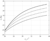 |
Fig. 4. Dependence of grain angle and angular velocity of the disc on different values of the throwing blade direction ω2 =- 15 c−1: dashed line – β =10°, breaking line – β =20°, dotted line – β =30°, continuous line – β =40°. |
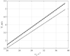 |
Fig. 5. Dependence of the normal component of the rate of return on the impact and angular velocity of the disc: breaking line – ω2 =-15 c−1, β =10°; continuous line- ω2 =-5 c−1, β =10°; dashed line – ω2 =-5 c−1, β=30°. |
4 Conclusion
As a result of the carried out researches it is possible to draw a conclusion that the size of a velocity of a shock deck in the greatest degree is defined by an angular speed of rotation of a disks and practically independent tugular speed of a decks, an an anatomical direction of speed of grain at a blow mainly depends on an angular speed of rotation of a decks and curvature of a blade at a disk edge. On this basis, it is possible to control the operation of the desiccant by changing the angular velocities of the disk and deck, thus influencing the direction of the grain impact on the deck and the magnitude of the impact interaction, which ultimately allows to create optimal conditions for desquamation.
References
- K.O. Potapov, L.R. Kadyrova, G.N. Galiullina, F.Z. Kadyrova, A.T. Khusnutdinova, I.Yu. Nikiforova, Morphological features and economic value of buckwheat varieties with physiological determination of growth J. of Pharmacy Research 11, 1252 (2017) [Google Scholar]
- R.I. Ibyatov, A.V. Dmitriev, R.S. Lotfullin, Grains movement research in the working space of pneumomechanical silencer Technics and equipment 2, 18–21 (2018) [Google Scholar]
- A.V. Dmitriev, E.G. Nurullin, Theoretical determination of the desiccant energy on the basis of pneumomechanical grain silencers Bulletin of Kazan State Agrarian University 61(19), 101–102 (2011) [Google Scholar]
- E.G. Nurullin, Pneumomechanical silencers of grain (theory, construction, calculation) 308 (Kazan university, Kazan, 2011) [Google Scholar]
- D. N. Kotov, Yu. M. Isaev, N. P. Kryuchin, N. M. Semashkin, A. N. Kryuchin, Determination of speed of movement of the particle on the rotating cone with shovels Int. J. of mechanical engineering and technology, 10(2), 1507–1514 (2019) [Google Scholar]
- A. Belinsky, B. Ziganshin, A. Valiev, D. Haliullin, I. Galiev, N. Adigamov, Theoretical investigation of increasing efficiency of combine harvester operation on slopes Engineering for Rural Development 18, 206–213 (2019) DOI: 10.22616/ERDev2019.18.N252 [Google Scholar]
- D.T. Khaliullin, E.G. Nurullin, Research of grain movement in confusor pneumo-mechanical destruction of sunflower seeds Bulletin of Kazan State Agrarian University 54(18), 122–124 (2010) [Google Scholar]
- N.I. Seomushkin, B.G. Ziganshin, S.M. Yakhin, B.A. Gayfullin, R.E. Vlasov, Mathematical model of interaction of seeds with the internal surface of sowing block of seed drill in Science, Technology and Higher Education 531–535 (Strategic Studies Institute, Westwood, Canada, 2012) [Google Scholar]
- D.A. Gubaidullin, V.L. Fedyaev, I.V. Morenko, Non-Isothermal Flow Around Rotating Bodies by Disperse Media Physical-Chemical Kinetics in Gas Dynamics 16(3), 69–79 (2015) [Google Scholar]
- L.P. Kholpanov, R.I. Ibyatov, Mathematical modeling of the dispersed phase dynamics Theoretical Foundations of Chemical Engineering 39(2), 190–199 (2005) [CrossRef] [Google Scholar]
- R.I. Nigmatulin, Dynamics of multiphase media. Part 1 464 (Nauka, Moscow, 1987) [Google Scholar]
All Figures
|
Fig. 1. Sheller scheme with rotating deck: 1 – paddle plate (rotor); 2 – deck. |
| In the text | |
|
Fig. 2. To the conclusion of the trajectory equation. |
| In the text | |
|
Fig. 3. Dependence of the grain impact angle on the disc rotation speed at different values of the deck rotation angular speed for β =10°: dashed line – ω2 = – 15 c−1, breaking line – ω2 =-10 c−1, solid line – ω2 = –5 c−1. |
| In the text | |
|
Fig. 4. Dependence of grain angle and angular velocity of the disc on different values of the throwing blade direction ω2 =- 15 c−1: dashed line – β =10°, breaking line – β =20°, dotted line – β =30°, continuous line – β =40°. |
| In the text | |
|
Fig. 5. Dependence of the normal component of the rate of return on the impact and angular velocity of the disc: breaking line – ω2 =-15 c−1, β =10°; continuous line- ω2 =-5 c−1, β =10°; dashed line – ω2 =-5 c−1, β=30°. |
| In the text | |
Current usage metrics show cumulative count of Article Views (full-text article views including HTML views, PDF and ePub downloads, according to the available data) and Abstracts Views on Vision4Press platform.
Data correspond to usage on the plateform after 2015. The current usage metrics is available 48-96 hours after online publication and is updated daily on week days.
Initial download of the metrics may take a while.