| Issue |
BIO Web Conf.
Volume 17, 2020
International Scientific-Practical Conference “Agriculture and Food Security: Technology, Innovation, Markets, Human Resources” (FIES 2019)
|
|
|---|---|---|
| Article Number | 00118 | |
| Number of page(s) | 6 | |
| DOI | https://doi.org/10.1051/bioconf/20201700118 | |
| Published online | 28 February 2020 | |
Study of the influence of the oncoming flow of soil on the screw surface of a subsoiler
1
Kazan State Agrarian University, 420015 Kazan, Russia
2
Vyatka State University, 610000 Kirov, Russia
3
Vyatka State Agricultural Academy, 610017 Kirov, Russia
* Corresponding author: This email address is being protected from spambots. You need JavaScript enabled to view it.
Abstract
Establishing optimal technological and design parameters of tillage tools is essential for ensuring tillage quality and lowest possible energy consumption by the tillage process. For simple plane soil looseners, used on the majority of tillage machines, this task is successfully achieved. In the meanwhile, significant proportion of tillage machines has relatively complex tools, which combine translational motion of the tool with rotation around its axis. This article studies the process of soil interaction with a screw conical subsoiler mounted on bearings. The subsoiler can freely rotate around its axis. The surface of the subsoiler is described by the screw surface equation bounded by a circular cone. External action on the subsoiler body is a resultant of normal and tangential forces applied to screw surface and friction force in the bearings. Theoretical dependencies have been obtained which determine the resultant force of soil on the screw surface of the subsoiler. This force is composed of the sliding friction force and the force appearing due to frontal soil flow after destruction of soil structural cohesion. The article also gives results of numerical calculations. The obtained dependencies allow studying the influence of technological and design parameters of the screw tool on the tillage process and substantiate parameters’ optimal values.
© The Authors, published by EDP Sciences, 2020
 This is an Open Access article distributed under the terms of the Creative Commons Attribution License 4.0, which permits unrestricted use, distribution, and reproduction in any medium, provided the original work is properly cited.
1 Introduction
Analysis of the development of modern tillage machines indicates that reactive tillage tools with screw surface attract much attention as this kind of tools makes it possible to decrease drag force and consequently reduce energy consumption of tillage process [1–7].
The purpose of the study is to determine the external forces appearing from the oncoming flow of soil, which act on the screw surface of the conical tillage tool. The tool constitutes a screw conical subsoiler on bearings, which has the ability to rotate around its own axis if a certain amount of force is applied to the screw [8–10].
The action of soil on screw surface can be represented by three components. The first one arises as a result of soil flow deformation prior to its structure cohesion destruction. The second one is determined by the change of momentum of the soil flow, which, in the coordinate system linked to the tillage machine, acts on each element of area of the screw surface and after interaction with it slides along the surface. The third component of the soil action is connected with friction forces appearing as a result of soil particles sliding on the screw surface in the direction of the projection with the initial velocity of the oncoming soil flow on this surface [11].
In [12] the action of soil on the screw surface of the subsoiler prior to the destruction of soil structure cohesion was studied. This article studies the second and third resulting forces connected with the action of the oncoming flow of soil and sliding friction force.
2 Materials and methods
The tool is designed to perform subsoil loosening of the soil and is a screw cone subsoiler mounted on a rack by means of bearings (Figure 1). The subsoiler has the ability to rotate around its axis when a certain amount of force is applied to the screw [13].
Let us study the rotational motion of a rigid body, which moves in the soil and interacts with the oncoming flow. The translational component of this movement has a constant horizontal velocity equal to the velocity of movement of the machine. In inertial, progressively moving axes, the body is hinged on the axis of rotation z. The z axis is inclined to the horizon at an angle (ψ/2+ε), where ε is the angle between the lower generatrix of the subsoiler cone and the horizontal plane, y is the angle at the vertex of the cone. The oncoming flow of soil in the reference frame linked to the tillage machine deviates from the undisturbed motion. It flows around the surface of the tool’s body and forces it to turn on an axis (Fig. 2) [14].
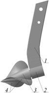 |
Fig. 1. General view of the screw cone subsoiler: 1 – rack; 2 – bearing unit; 3 – cone; 4 – screw wings |
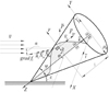 |
Fig. 2. Flow of soil. |
3 Results
The surface of the subsoiler is described by the equation of a screw surface bounded by a circular cone (Fig. 2).
In a cylindrical coordinate system (ρ, ϕ, z), a screw surface can be described by the equation (1)
(1)
where a is the proportionality coefficient, which determines the pitch of the screw along the z axis, equal to 2πa and taken as constant.
The direction of the normal to the screw surface is determined by the vector gradient (2)
(2)
where f =z -aϕ.
After calculating the partial derivatives, the vector gradient will take the following form (3)
(3)
The modulus of this gradient vector is (4)
(4)
The external action of the oncoming flow on the tool’s body is reduced to normal and tangential forces from the soil applied to the screw surface, as well as to normal reactions and friction forces in bearings on the axis of rotation. To calculate these forces, it is necessary to know the angle between the oncoming flow direction and the screw surface, as well as the velocity of this flow.
In [12], the following dependence was obtained for calculating the angle: (5)
(5)
where α is the angle between the normal to the surface and the direction opposite to the soil flow velocity.
The flow velocity vector in a cylindrical coordinate system is determined as [12]: (6)
(6)
Let us select the i-th element of area dS on the screw surface. Let us consider how the second component of the normal reaction is determined, due to the change in the momentum of the soil flow, which runs on each element of area of the screw surface. According to the theorem on the change of momentum [14] in the projection on the normal to the tangent plane, carried out in the i-th point, we obtain: (7)
(7)
where Niv is the value of the normal reaction of the element of area dS to the speed of the oncoming soil flow; Qi is the momentum of soil particles after interaction with the surface in the projection on the normal to it, Qi is the momentum of soil particles before interacting with the surface in the projection on the normal; dt is interaction time.
At a steady state, the interaction time may be taken as equal to 1. (8)
(8)
The mass of the flow of soil of density γ, interacting with the element of area dS equals: (9)
(9)
Then (10)
(10)
The momentum of soil particles after interaction with the surface in the projection on the normal to it is 0, because after the interaction the soil slides along the surface in a tangent plane: (11)
(11)
Substituting (10) and (11) into (7), we get (12)
(12)
Canceling out dt, let us find the value of the normal reaction of the element of area dS from the second component of the soil action on the subsoiler (13)
(13)
The force Niv creates a torque around the axis of rotation of the tool’s body, as well as axial force projected on the z axis. The magnitude of the torque is equal to the product of the projection of the force Niv on the direction  and coordinate ρ:
 (14)
(14)
The cosine of the angle between the normal n and the direction of the coordinate axis p is defined as the projection of the gradient to the surface divided by its module (15)
(15)
Then, the moment of reaction of the element of area dS with respect to the z axis is equal to (16)
(16)
To determine the moment of all reactions Niv, let us calculate the integral Mzv(Niv) of the screw surface of the subsoiler (17)
(17)
This surface integral is calculated through multiple integrals over another area Ω, which in turn is the projection of the screw surface onto the cones [12] (18)
(18)
When moving to multiple integrals, it is necessary to set the range intervals for parameters ρ and φ.
Two circular cones bound the screw surface of the subsoiler. Let the conditional circular cone, which limits the screw surface outside, be given by the equation (19)
(19)
where  is the angular coefficient;
z0 is the height of the cone, m; ρ0 is the radius of the base of the cone, m.
Let us set the screw surface as (20)
(20)
where  ; n is the number of screw turns.
Then, equating the right-hand sides of (19) and (20) for the upper boundary of the integral over the parameter ρ, we obtain (21)
(21)
The inner cone, on the outer part of which the screw surface is screwed, is given by the equation (22)
(22)
where  is the angular coefficient, ρc is the base radius, m.
Then, taking into account (20), we obtain the lower limit of the integral over the parameter ρ
 (23)
(23)
Thus, when compiling a multiple integral, the current radius ρ changes from  to
to  .
.
The parameter φ varies from zero to its final value, which depends on the number of turns. At the top of the cone ρ = 0, then from (21) we have  . Since
 and
and  , we finally get φ = 2πn. Consequently, proceeding to multiple integrals, the parameter p changes from 0 to 2πn.
The obtained integration boundaries are valid for the screw surface, which has a zero angular coordinate on the plane of the cone’s base. When the conical subsoiler rotates, the location of the screw surface changes, which leads to changes in the boundaries of integration. Let us denote the angular coordinate of the screw on the plane of the base of the cone by φn. Then the angular coordinate φ will change from φn to φk=φn + 2πn. In this case, the current radius ρ should change from ρn = ρc -α/kc(φ-φn) to ρk= ρ0 -a/k(φ-φn).
After proceeding to multiple integrals, the surface integral will take the following form (24)
(24)
The torque of soil pressure forces on the screw surface from the change in the momentum MDzv, respectively, will change the sign MDzv=-Mzv.
Let us define the constraint along the z axis, which is created by the oncoming soil flow force Niv and calculate the cosine of the angle between the normal  and the unit vector
  .
. (25)
(25)
Then the total reaction is determined through the surface integral (26)
(26)
After proceeding to multiple integrals taking into account (18), we get (27)
(27)
Note that if a subsoiler has several screw surfaces, the corresponding normal forces and torques for each of them are calculated separately and then summed.
Let us turn to the third component of the soil flow force applied to the screw surface, i.e. to the friction forces. Sliding friction occurs under the condition of relative movement of the soil along a screw surface. This condition is satisfied if the elevation angle of the screw at the surface boundary is greater than the friction angle associated with the coefficient of friction on the soil ftr.
At the points of the screw lying closer to the axis z, this condition will certainly be fulfilled. With a constant pitch of the screw, taking into account the taper of the surface bounding the screw, it can be stated that the smallest angle of elevation of the screw is at a point with coordinates ρ = ρ0, ϕ= 0, z = 0. Then the slide condition at all points on the surface will take the form (28)
(28)
We assume that the elementary friction force applied to the element of area dS is proportional to the sum of normal reactions from the first two components with a friction coefficient ftr and directed along the projection of the initial flow velocity on the tangent plane to the element of area. Then the magnitude of the friction force applied to the area dS is equal to [12] (29)
(29)
To find the magnitude of the velocity projection on the tangent plane to the sliding surface  , we first calculate its projection onto the normal to the surface. The cosine of the angle between the normal
  and the flow velocity vector is determined based on the scalar product of these vectors [12]. Then the normal component of speed will take the form
 (30)
(30)
Since the normal velocity vn is perpendicular to the tangent plane, the value vτ is determined by the Pythagorean theorem: (31)
(31)
The friction force Fitr needs to be expanded along the axes of the cylindrical coordinate system. Since the friction force always points towards the relative velocity, in order to find the components of the friction force, we use the decomposition of velocity along the axes. Let us write the expression of speed through the unit vectors of these axes (32)
(32)
The components of the flow velocity along the axes were obtained in [12]. In this article, they are presented as part of expression (6).
For each component of the soil flow rate, we also determine the projection of the normal to the surface: (33)
(33)
 (34)
(34)
 (35)
(35)
Similarly, with (31) let us define the projections of the velocities on the tangent plane (36)
(36)
 (37)
(37)
 (38)
(38)
Since the projections of the friction force on the cylindrical axes correspond to the components of the tangential velocity along these axes, the friction force vectors and the tangential velocity are collinear. Let us write the conditions of collinearity of vectors (39)
(39)
Hence (40)
(40)
The modulus symbol in expressions is determined by the method of finding the tangential component of the flow velocity through the difference of the squares of the full and normal component.
Let us integrate the torque of friction forces around the axis z, given that it creates only the component Fitrϕ in the direction  with the shoulder ρ:
 (41)
(41)
The sign of the moment is negative if ![Mathematical equation: $ \varphi \in \left[ {0 \ldots \frac{\pi }{2}] \cup [\frac{3}{2}\pi \ldots 2\pi } \right] $](/articles/bioconf/full_html/2020/01/bioconf_fies2020_00118/bioconf_fies2020_00118-eq56.gif) and positive for the other angle φ ranges on the first turn of the screw. On subsequent turns, the sign of the moment changes in the same way.
and positive for the other angle φ ranges on the first turn of the screw. On subsequent turns, the sign of the moment changes in the same way.
Using the expression of the friction force through normal reactions to the surface, taking into account (5) we obtain: (42)
(42)
Integrating the components of the friction forces in the direction of the axis z, we obtain: (43)
(43)
Similarly, in the radial direction ρ, we get: (44)
(44)
The total constraint along the z axis is defined as the sum of the three components: (45)
(45)
Traction force is equal to: (46)
(46)
The force Nzσ that arises during the deformation of the soil flow before the destruction of the cohesion of its structure was previously determined in [12]. It can be calculated in the same way as the force of the oncoming flow, if in formula (27) the product γv2 is replaced by the coefficient of the maximum compression stress σ .
The total reaction in bearings is determined by the magnitude, as the geometric sum of all reactions from forces and friction forces normal to the surface. Given the fact that the radial sum of normal reactions is zero, we get (47)
(47)
The torque of friction forces in a bearing of radius ρp and friction coefficient fp, is determined by the formula: (48)
(48)
The total torque relative to the axis of rotation of the working body is calculated as the sum of the four components (49)
(49)
where the last component is not a force resulting from the flow of the soil. It characterizes friction on the axis of rotation.
Using the obtained dependencies, numerical calculations were performed. Fig. 3, 4 show some results of numerical calculations for fixed values of the following parameters: z0 = 0.15 m; ρ= 0.02 m; ρ0 = 0.06 m; v =1.39 m / s (5 km/h); ρm = 1200 kg/m3; σ=50 000 N/m2; ftr =0.5; fp = 0.1; ρp = 0.03 m.
It was assumed that the conical subsoiler has three screw surfaces that are equidistant from each other. The initial angular coordinates of the screw surfaces on the plane of the base of the cone were 00, 1200, and 2400. The number of turns changed from 0.1 to 0.5. With the geometry of the subsoiler used, the angle at the tip of the cone was ψ = 440. The cutting angle s, that is, the angle between the lower generatrix of the subsoiler cone and the horizontal plane, varied from –220 to 100. The accepted minimum cutting angle, equal to –220, corresponds to the horizontal position of the axis of rotation of the subsoiler. All angular values in the calculations and in the figures were presented in radians.
Fig. 3 shows the traction force NTY at different numbers of screw turns n and different values of the cutting angle ε. Corresponding lines of equal values are presented in Fig. 4. With an increase in the number of turns n, the area of the screw surface increases, which in turn leads to an increase in the sliding friction force and the forces of the oncoming flow of soil. Therefore, as the number of turns n increases, the traction increases as well.
The effect of the cutting angle ε on NTY is more complex and depends on the length of the screws n. With a small length of the screw, a certain amount of the cone remains without a screw surface. In this case, an increase in the cutting angle leads to a decrease in traction. Whenthe number of turns is greater than 0.33, some of the three-wing screw cone generatrixes will be crossing two screw surfaces. In this case, as can be seen from Fig. 3, the traction begins to increase. The optimal cutting angle that provides the smallest value NTY increases with increasing screw length.
The effect of the number of turns and the cutting angle on the torque value is shown in Fig. 4. As the parameters n and s increase, the torque acting on the conical subsoiler grows. It is not difficult to notice that the increase in torque is monotonous.
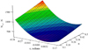 |
Fig. 3. The dependence of traction on the number of turns n and cutting angle ε |
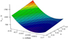 |
Fig. 4. Dependence of torque on the number of turns n and the cutting angle ε. |
4 Conclusion
As a result of the study, theoretical dependences were obtained to determine the force from the soil acting on the screw surface of the subsoiler, which is caused by sliding friction forces and the soil flow forces after the destruction of the cohesion of soil structure. The dependences obtained allow us to carry out a computational experiment with different values of the design and technological parameters of the screw subsoiler taking into account the specific physical and technological properties of the soil. Thus, the constructed mathematical model, which takes into account the forces of deformation of the soil flow before the destruction of the cohesion of soil structure, as well as the forces associated with the oncoming flow of soil on the screw surface and the forces of sliding friction after soil destruction, can be used to substantiate the optimal parameters of the screw tools of tillage machines.
References
- V. Moskalevich, MOTROL 11B, 179–189 (2009) [Google Scholar]
- I. Ahmadi, Soil and Tillage Res. 171, 1–8 (2017) [CrossRef] [Google Scholar]
- O.A. Fouda, J. Soil Sci. and Agric. Eng. Mansoura Univ. 7, 929–936 (2016) [Google Scholar]
- V.P. Mazyarov, V.I. Medvedev, G.Z Gaifullin, L.P. Shershevsky, publ. Auth. St, no. SU 1373336, Bull. Izobret. 6 (1986) [Google Scholar]
- Deep diggers give a high lift to yields Farmers Weekly 115, 42 (1991) [Google Scholar]
- G. Sabourin, J. Richardeau, Patent FR, no. 9115937 (1993) [Google Scholar]
- V.P. Mazyarov, V.I. Medvedev, The sub-cover ripper significantly reduces energy consumption during tillage (2013) Retrieved from: http://www.polytech21.ru/news/1846-podpokrovnyj-rykhlitel-znachitelno-snizhaet-energozatraty-pri-pochvoobrabotke [Google Scholar]
- A.P. Akimov, Yu.V. Konstantinov, Tractors and agricultural machinery 12, 21–23 (2015) [Google Scholar]
- S.A. Sidorov, V.K. Horoshenkov, D.A. Mironov, E.S. Luzhnova, Tractors and agricultural machines 8, 30–32 (2016) [Google Scholar]
- A. Valiev, F. Muhamadyarov, 15-th Int. Sci. Conf. Engineering for Rural Development Proc. 15 1378–1385 (Latvia University of Agriculture, Faculty of Engineering, 2016) [Google Scholar]
- M.N. Letoshnev, Agricultural machines. Agricultural equipment. Theory, calculation, design and testing (Moscow, 1955) [Google Scholar]
- I.S. Mukhametshin, A.R. Valiev, A.V. Aleshkin, R.I. Ibyatov, Bull. of the Ulyanovsk State Agricult. Acad. 4, 50–182 (2018) [Google Scholar]
- I.S. Mukhametshin, A.R. Valiev, P.I Makarov, Patent of RF, no. RU 2522320, Bull. Izobret. 19 (2013) [Google Scholar]
- N.N. Nikitin, The course of theoretical mechanics (Higher School, Moscow, 1955) [Google Scholar]
All Figures
|
Fig. 1. General view of the screw cone subsoiler: 1 – rack; 2 – bearing unit; 3 – cone; 4 – screw wings |
| In the text | |
|
Fig. 2. Flow of soil. |
| In the text | |
|
Fig. 3. The dependence of traction on the number of turns n and cutting angle ε |
| In the text | |
|
Fig. 4. Dependence of torque on the number of turns n and the cutting angle ε. |
| In the text | |
Current usage metrics show cumulative count of Article Views (full-text article views including HTML views, PDF and ePub downloads, according to the available data) and Abstracts Views on Vision4Press platform.
Data correspond to usage on the plateform after 2015. The current usage metrics is available 48-96 hours after online publication and is updated daily on week days.
Initial download of the metrics may take a while.